Alternative wide table mounting methods

Collapse
This topic is closed.
X
X
 
  • Time
  • Show
Clear All
new posts
  • chopnhack
    Veteran Member
    • Oct 2006
    • 3779
    • Florida
    • Ryobi BT3100

    Alternative wide table mounting methods

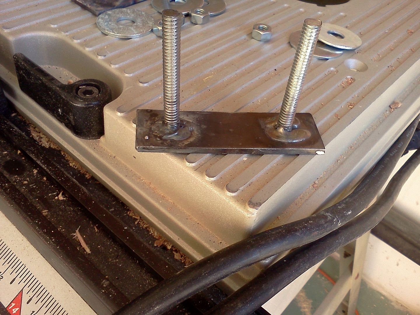
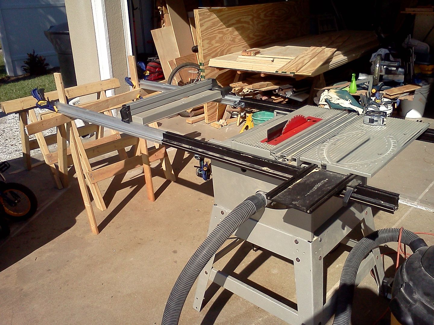
    Ok, so you need to crosscut large pieces 30+" wide and you have no specialty t-nuts, what do you do?

    I will post some pics of what I did after we have some interesting posts
    I think in straight lines, but dream in curves
  • Black wallnut
    cycling to health
    • Jan 2003
    • 4715
    • Ellensburg, Wa, USA.
    • BT3k 1999

    #2
    I have know of at least one member that milled 6 inch long connecter plugs that matched the inside rail profiles.
    Donate to my Tour de Cure


    marK in WA and Ryobi Fanatic Association State President ©

    Head servant of the forum

    ©

    Comment

    • mpc
      Senior Member
      • Feb 2005
      • 981
      • Cypress, CA, USA.
      • BT3000 orig 13amp model

      #3
      No wide table kit & mounting hardware? Then I'd make and use a sawboard for my circ saw.

      As for the wide table kit, I did have the Ryobi hardware on it for a while but the metal plates got in the way for my infeed/outfeed tables that slide in the bottom portion of the rails. So I used some hard maple and aluminum angle bracket as a stiffener to make pieces that fit inside the rails, then drilled countersunk screws into the back and bottom of the rails. Now the hardware is completely buried inside the rails and doesn't block anything from sliding in the rail tracks.

      I've also used 1 inch steel flat bar stock since that just fits in the rails, then spot-welded a smaller layer onto that - making a squat T-shaped cross section 2-layer bar stock. I then drilled and tapped a few holes for standard Ryobi screw-knobs. Nice long replacements for T-nuts that helped hold the rails together - and helped with the alignment since it bridged the junction. Stiffer than a couple T-nuts. These too were replaced by the inside-the-rails pieces described above.

      mpc

      Comment

      • chopnhack
        Veteran Member
        • Oct 2006
        • 3779
        • Florida
        • Ryobi BT3100

        #4
        I have used the sawboards for breaking down sheet goods, but sometimes I get an angled cut instead of a 90 degrees on the cut face. I may just be deflecting the blade by pushing too hard laterally or the sheet good may have a bow in the particular spot when I am cutting.

        That is not the only reason why I wanted to use a t.s. for the cuts, its the repeatability and speed the t.s. affords when doing this kind of work.

        I like your milled piece that fits inside, that sounds like it would help create a lot of stiffness!! That is what my 5 minute getup lacked and I felt that there was too much play causing the fence to lock out of square. I do think that if this was a permanent fixture, it would need to be supported in two spots.

        Needless to say the pieces got cut up and ready for production so I am happy. I wouldn't use the same setup again though.

        MPC, do you have pictures of your solution?


        I think in straight lines, but dream in curves

        Comment

        • JimD
          Veteran Member
          • Feb 2003
          • 4187
          • Lexington, SC.

          #5
          I just took my wide table off in preparation to a move with a much smaller shop available. I also have a track saw so I don't think I need the wide table any more (although I plan to keep the rails and probably my mounting hardware).

          I mounted the rails to the accessory table with 1/8 inch bar in the slot drilled and tapped with knobs (the knobs had 5/16 studs). I also mounted the accessory table to the table saw base with flat stock in the bottom of the rails which was also drilled and tapped. Mounting this way let me slide the table although the only reason I did that was to tilt the saw up for cleaning. It worked well. With my smaller setup (which is not finished) I will have an accessory table on the right mounted to the rails using a portion of the old setup. I moved the aluminum router table piece to the left of the blade although I had to modify it a little underneith for it to work. I do not use the SMT.

          Anyway, I don't think you need anything other than threaded flat stock. Handknobs will not strip the threads in my experience. Some of my flat stock is aluminum.

          Jim

          Comment

          • Cochese
            Veteran Member
            • Jun 2010
            • 1988

            #6
            I need to get some longer bolts and some washers or nuts. I took my router table and mounted it to the rail extensions and it ended up closing the rails to the point that the back of the rip fence wouldn't lock. I couldn't move the table mounts further outboard or the rip fence wouldn't clear them.

            It wouldn't have killed them to make the bolts just a tad bit longer with a few extra washers.
            I have a little blog about my shop

            Comment

            • mpc
              Senior Member
              • Feb 2005
              • 981
              • Cypress, CA, USA.
              • BT3000 orig 13amp model

              #7
              Originally posted by chopnhack
              MPC, do you have pictures of your solution?
              I will in a couple days. Right now the woodworking half of my shop+garage is compressed to expand the "car" side a bit. Once the engine is back in the car and verified running right (with no leaks) I'll restore the shop and will have enough room to separate the rails and take pics. In theory the car is done... just need to run/test it.

              mpc

              Comment

              • chopnhack
                Veteran Member
                • Oct 2006
                • 3779
                • Florida
                • Ryobi BT3100

                #8
                Originally posted by mpc
                I will in a couple days. Right now the woodworking half of my shop+garage is compressed to expand the "car" side a bit. Once the engine is back in the car and verified running right (with no leaks) I'll restore the shop and will have enough room to separate the rails and take pics. In theory the car is done... just need to run/test it.

                mpc
                Re-ring? or tranny work?
                I think in straight lines, but dream in curves

                Comment

                • mpc
                  Senior Member
                  • Feb 2005
                  • 981
                  • Cypress, CA, USA.
                  • BT3000 orig 13amp model

                  #9
                  It's a 25 year old car with 89K on the clock. The aluminum in the cyl head actually eroded from the inside-out. It didn't corrode or rot - it literally wore away. You can actually see eroded corners when eyeballing through some of the cooling jacket openings. Eventually a spot got thin and porous enough to let coolant into the #4 cylinder so the exhaust suddenly became a huge white cloud. The machine shop that checked the head said they've seen this before on a different manufacturer's engine too. Anyway, I ended up having to get a new cyl head. The machine shop was going to need a few days to get the new head & move my valves, camshaft, etc. over to it and, since the engine was getting close to the 100K service interval, I decided to pull the block to:
                  a) replace the timing chains (yup - chains plural: one for the camshaft, and a smaller one for balance shafts and the oil pump)
                  b) replace the clutch
                  c) re-do all o-rings, gaskets/seals, etc. too just because parts that were once upon a time rubber were now more like hard plastic. I guess I goofed one o-ring because I ended up with a small oil leak near the oil filter mounting boss. That area is re-done now but I haven't fired up the car to check for any more leaks or if that in fact fixed the problem. Gotta clean up my catch-pan first so I can see if it catches anything new or not.

                  mpc

                  Comment

                  • LCHIEN
                    Internet Fact Checker
                    • Dec 2002
                    • 21011
                    • Katy, TX, USA.
                    • BT3000 vintage 1999

                    #10
                    friend had a vintage Caddy Allante with an aluminum engine block - about the same age. He mostly parked it and it sat in his garage. You gotta change the coolant periodically even when sitting because it will corrode the engine block away! Expensive repairs!
                    Last edited by LCHIEN; 10-30-2013, 12:41 AM.
                    Loring in Katy, TX USA
                    If your only tool is a hammer, you tend to treat all problems as if they were nails.
                    BT3 FAQ - https://www.sawdustzone.org/forum/di...sked-questions

                    Comment

                    • chopnhack
                      Veteran Member
                      • Oct 2006
                      • 3779
                      • Florida
                      • Ryobi BT3100

                      #11
                      Wow, that is interesting. I wonder if the current alloys being used are more resistant to the abrasion?
                      I think in straight lines, but dream in curves

                      Comment

                      • mpc
                        Senior Member
                        • Feb 2005
                        • 981
                        • Cypress, CA, USA.
                        • BT3000 orig 13amp model

                        #12
                        The engine design in this car was originally developed as a propane powered diesel engine for Japanese forklifts. Then the design was adapted to be a gasoline car engine with a carburetor. It was used in many different models (and a couple different brands) of vehicles as a carb engine in the 1970s and 1980s. Around 1983 the design was tweaked to be a turbocharged and throttle body fuel injected engine. All through this time frame - a couple decades roughly - the basic block, crank, etc. remained fundamentally unchanged; only the oil pump pick-up point was changed (options for RWD or FWD vehicles) and some bolt-holes for accessories got added over time. The cyl head design went through several significant changes however... adapting the whole engine to the different fuels for each variation/derivative of the original engine. A port fuel injected version, with an all-new intake manifold, was even used well into the 1990's in Australia.

                        In 1988 (the year of my car) the turbocharger max output pressure was bumped up a bit for more horsepower so lots of things on the car were beefed up from prior model years: stronger transmission 1st & 2nd gears, a stronger transmission case, a larger diameter clutch disk and pressure plate, beefier drive axles, a higher-flowing water pump, etc. And the material composition of the cyl head was changed: something was changed in the aluminum mix for the 88-90 model years (last years of this particular model's run) and some interior casting shapes were altered. Looking closely at it, it's clear there were eddy currents (circular water flow) in spots - concentrating the erosion. The coolant that was in the vehicle wasn't old; I'm pretty good at keeping up with the routine/scheduled maintenance on my vehicles. The machine shop has seen other cyl heads internally eroding from age without showing signs of corrosion or galvanic reactions (i.e. not showing signs of neglected coolant) from other Japanese vehicles of roughly the same vintage.

                        mpc

                        Comment

                        • mpc
                          Senior Member
                          • Feb 2005
                          • 981
                          • Cypress, CA, USA.
                          • BT3000 orig 13amp model

                          #13
                          Originally posted by chopnhack
                          MPC, do you have pictures of your solution?

                          I will in a couple days. Right now the woodworking half of my shop+garage is compressed to expand the "car" side a bit. Once the engine is back in the car and verified running right (with no leaks) I'll restore the shop and will have enough room to separate the rails and take pics. In theory the car is done... just need to run/test it.

                          mpc
                          Okay, finally got the shop back and took a few pictures. The insert started as a 1 inch by 1 inch by foot long corner aluminum piece from the Borg. One side that ended up vertical in my assembly got cut down to about 3/4 inch to fit inside the BT3 rail. Then I screwed a piece of hard maple scrap to the aluminum to help stiffen it. This assembly was then screwed to the rails with 8 screws set in countersinks through the bottom and backsides of the BT3 rails. Seems to hold fine though it clearly isn't enough to let the rails hang free - they need their own legs on the far end. The rear rail has a pretty similar setup, just sized slightly differently to fit inside the rear rail. Since I screwed these to the rails, they are not form-fitted to the inside cross section of the rails, just roughly rectangular to snug fit in the main portion of each rail. Notice in the first pic a small black mark is visible in the center of the aluminum; that lines up with the end of the BT3 rail when I'm putting things together to help me find the screw holes. And I ended up needing a little foil tape on one end as my BT3 rails didn't want to line up perfectly... I guess the thickness of the walls isn't exactly the same. The Ryobi mounting pieces index off the outside of the rails, thus guaranteeing they'll line up. Mine index off the inner walls... not so precise. Also, watch where you drill the holes for the screws that attach the assembly to the BT3 rails - make sure you don't put a screw into one of the screws holding the wood to the aluminum!

                          The small black thing in the 3rd pic are a sample of my home-made long T-nut. (T-bar?) Basically a 1 inch wide piece of steel that just fits into the BT3 rails, and a narrower piece (was a pain to cut) welded to it. In the pic, my home-made bit is on the left... the "tapers" visible on the ends are the actual welds. If you look closely at the top, between the two screw holes, you can see a circular shaped mark or highlight in the material; that was another hole drilled in the top piece so I could spot-weld the two pieces together in the center. Then I powder coated the assembly. Next, I made two holes drilled and tapped to match up with the Ryobi cap piece from the wide table kit. I used taps that match the threads on the Ryobi hardware. A thick block of aluminum or steel would work just as well for the cap piece; I happened to have some of the Ryobi bars so I used them... I just didn't have enough T-nuts and when I thought about getting more I figured one long T-bar, bridging the two rail sections, would be stiffer/stronger than two separate T-nuts. Two T-nuts might pivot like a link in a chain unless they're really tight... at least that was my thinking.

                          mpc
                          Attached Files

                          Comment

                          • chopnhack
                            Veteran Member
                            • Oct 2006
                            • 3779
                            • Florida
                            • Ryobi BT3100

                            #14
                            Ah! Picture worth a thousand words, thanks MPC!! That is a good setup and I am sure stiffened up the assembly substantially. I will have to look at mine since the two rails are different, one is the newer black rail and the other the older silver rail.

                            Thank you!
                            I think in straight lines, but dream in curves

                            Comment

                            • dbaudo1
                              Forum Newbie
                              • Nov 2011
                              • 16
                              • Tucson, AZ
                              • Ryobi BT3000

                              #15
                              Hey Chop,

                              If you bite off on this one, please take pics. I'm in the same boat as you with one set silver and one black.

                              MPC, correct me if I'm wrong but the t-nut you made is not used to connect the rails, right? If I understood correctly, you just drilled the existing rail and countersink the screws which bite into the angle/maple piece. Is that right.

                              Dom

                              Comment

                              Working...