

This is one really nice program.
-
Deep in the Darkside -
First one is how to model the thickness of say, shelves and carcass for a book case? I assumed you would just draw a line 3/4" (or whatever thickness you want) away from and parallel to another line. I could not draw 2 lines that close together. I think 1.25" was about as close as I could get them. I tried zooming in and moving one line, but that didn't work.Originally posted by davidtu
Any suggestions on this one?
Thanks!JohnComment
-
Nice Program
Quick and easy program to use. I sketched this is 15 minutes using pre-drawn models for the shelving unit, the utility sink and the lockers.
I took the legs off the sink and wrapped a skirt around it. I don't think I got it completely straight but a lot better then I could draw.Attached FilesLast edited by greencat; 04-28-2006, 06:50 AM.Thanks again,
MikeComment
-
-
I resisted downloading this when it was $499. I thought if it was as good as people say, I would wind up trying to talk myself into buying it. This is going to be great for going through various designs on decks and sheds new to the house. I've used 3D animation software quite a bit in the past and I love the thickness dragging and other pieces to quickly prototype things. Using Ctrl+Tape measure or Protractor to leave a dashed line and build to that. Things go very fast.
It seems that this is designed for larger projects. I would also like to know tips for modeling smaller things. Also, is there and way to customize the tool bar? I would like to add Protractor and Measurement without having to have that toolbar open and thus duplicate icons.Joe SacherComment
-
Another Q:
I can't "select". I'm trying to change the length of the side of a rectangle by 1/4". It looks like I need to select, then use the scaling tool. Instructions say to use the select tool (little black arrow) by clicking on the "entity". The entity will highlight in yellow. However, when I click on the line with the select tool, it just turns blue.JohnComment
-
Can you use the move tool to move the edge of the rectangle in by 1/4"?Joe SacherComment
-
Tried that, but it jumps in increments greater than 1/4". So, the side is either too long or too short. Can't get it just right.Originally posted by sacherjjJohnComment
-
Go to the Window menu-Model Info-Units. You increase or decrease the Precision and Snapping there, as well as switching between Fractional, Decimal etc.Originally posted by jnesmithMike
Drywall screws are not wood screwsComment
-
Also, the more you zoom in (use your mouse wheel), the finer precision you can get with the tools.Comment
-
Looks like it's time for a ScetchUp forum. Oh, Sam, in your copious free time... Bob
Bob
Bad decisions make good stories.Comment
-
Mike
Drywall screws are not wood screwsComment
-
A very useful trick to know is that in the lower righthand corner Sketchup shows the dimensions of the current object. When you are in the MIDDLE of drawing an object, such as a rectangle, you can simply type the sizes you want the rectange to be.
So, click on the Rectangle tool... then start to drag out your rect.... then type in let's say "3.5,1.5". That will result in a rectangle 3.5" x 1.5". (Numbers w/o any indication of " or ' -- i.e. inches or feet-- are assumed to be inches... if you want feet, just type the single quote ' for feet as in 3.5',1.5')
Now, to make a piece of lumber such as a 2x4, you will begin by making a 3.5 x 1.5 rectangle as described above. Then use the Extrusion tool (that is the one that looks like a rectanuglar block w/ an arror on it). W/ Extrusion tool, click on the rectangle's face (it will highlight w/ blue dot pattern) and move the mouse in the desired direction.
Now, an important thing to note in SU is that there are three axes... red, green and blue. The Blue is the vertical axis. When you make the rectangle you will have probably made it on the Red/Green plane as it is the easiest to draw on. When you extrude the rect it will move in the Z/blue/vertical axis. Now you will have a 3D "2x4".
SU has the concept of Components. A component is a standalone object. You will to make each "piece" of your project a component. That allows you to easily move it around and modify it.
TRIPLE click your 3D object created above. The entire object should be highlighted (blue dot pattern). Right click on it and choose Make Component. Optionally you can name it.
Now, you can use the Move tool (the crossed arrows) to move the object around. Its usually easiest to select the object first w/ the black arrow and then use the Move tool to move it around. As you move it you will note that you can drag it in any direction. However, if you drag in the green, red, or blue axis the dashed drag line will show in the appropriate color. Use this to make sure you are moving things around squarely. NOTE: when you want to move along an axis, start by dragging in that direction and when you hit up upon the colored axis line, press AND HOLD the SHIFT button while dragging and it will lock in the dragging to be on that axis.
Drag items from the corners, that way they will easily snap to other objects (at their corners) to make items align. You can even line up two objects w/o having them touch by using the SHIFT drag option mentioned above and simply moving the mouse over to a point on another object to which you wish to align. The drag will continue along the given axis but it will snap to the position of the point you put the mouse on the other object. Confused? I bet. It's hard to explain, easy to do. Say you have two 3D rectangles one 5" high, the other 10" high. If you want to move the 5" rect vertically to align at the top of the 10" high rect, you would click on the 5" rect, drag w/ the Move tool "upward" and when you see the blue dashed line (indicating you are on the blue/up axis) press SHIFT-and-HOLD and keep dragging. Now, move the mouse over to one of the topmost corners of the 10" rect. The 5" rect will have moved vertically parallel to the 10" rect. Done.
Another great thing to know is just as you can type the dimensions of an object while drawing it, you can also move an object by a certain amount by typing while dragging the object. So, an alternate way of aligning the tops of the above mentioned 5" & 10" rect, you could also have simply Moved the 5" rect and while dragging, once you get the blue axis, press SHIFT and hold it and then type in "5" and ENTER and it will move 5".
On getting the blue axis... sometimes its hard. While dragging "upward" try moving also to the left & right to try to "catch" the blue axis. Once you have it use the SHIFT to hold it. Sometimes you will need to change the perspective of the current view in order to more easily grab it. You can most easily rotate the view by clicking and holding the middle roller wheel... you have one, right? Or you can click on the view rotation tool (as arrows sort of in a figure-8), then use your left mouse button to change it.
Back to components.... say you've created a 10" 2x4, and now you want to make it 12". To do that... assuming you've made it a component as above... you will double click the component and it will go into component edit mode. Once in this mode, you will use all the tools as usual to change the size. To change the size of a 3D rect, you will drag the appropriate face using the Extrusion tool.
Now, here's the great part. Let's say you have 5 of those 10" 2x4s. First, you could have made them with COPY/PASTE or more quickly, you can make them by clicking on the original, choosing the Move tool and press the CTRL key. Drag w/ the CTRL key and you will make a copy of the 10" 2x4. There are tricks to make 5 copies, but for simplicity repeat that operation 4 times. Now suppose you want to change ALL 5 10" 2x4s to be 12" 2x4s. Since they are COMPONENTS as made above, you can just edit one of them as above, dragging one side 2" and ALL 5 instances of the component will also change!
(OK, OK, here is the copy trick... when you do the Move w/ CTRL key for the 1st copy, when you let go of the mouse, type in *4 and it will make 4 copies instead of just the one... they will be spread out according to how far you dragged the first one. This is a great trick for making a picket fence, for example!)
Ah... that's enough for now. Have I thoroughly confused everyone? Btw, the SKetchup website has great user forums just like here.Never met a bargain I didn't like.Comment
-
Thanks for all the help. I'm starting to get the hang of it.
The most useful tool for me, and probably other beginners, is the "undo" button. I recommend finding that one right quick.JohnComment
-
Great tips.. thanks for posting. One thing occured to me... would you want it to be nominal 2x4... or actual dimensions?Originally posted by davidtuComment
-
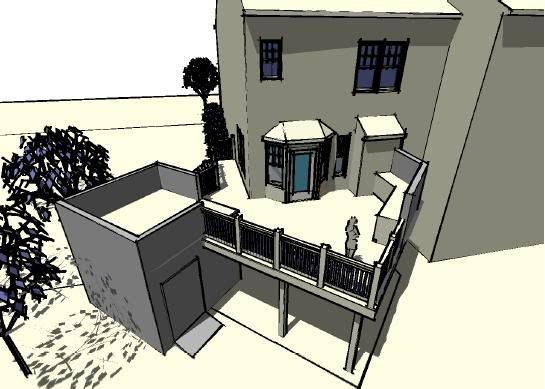
Great program...been using it for a little
I found it very easy to get a handle on...although I've got quite a few years of experience with CAD and modeling programs. I used it to design my deck, workshop and patio. Laying the patio tomorrow. Here it is:
 I like Wagoneers too. Hey...they've got wood
Comment


Comment