SMT travel

Collapse
This topic is closed.
X
X
 
  • Time
  • Show
Clear All
new posts
  • Heknits
    Handtools only
    • Oct 2013
    • 4
    • Benicia, CA
    • Ryobi BT3000

    SMT travel

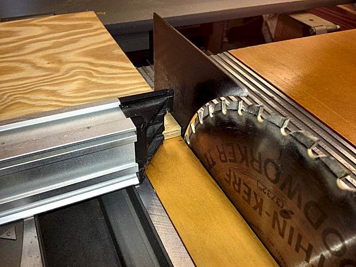
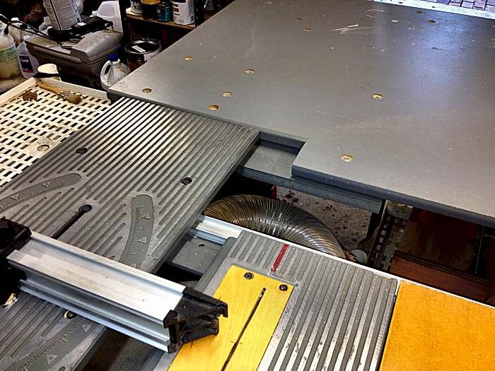
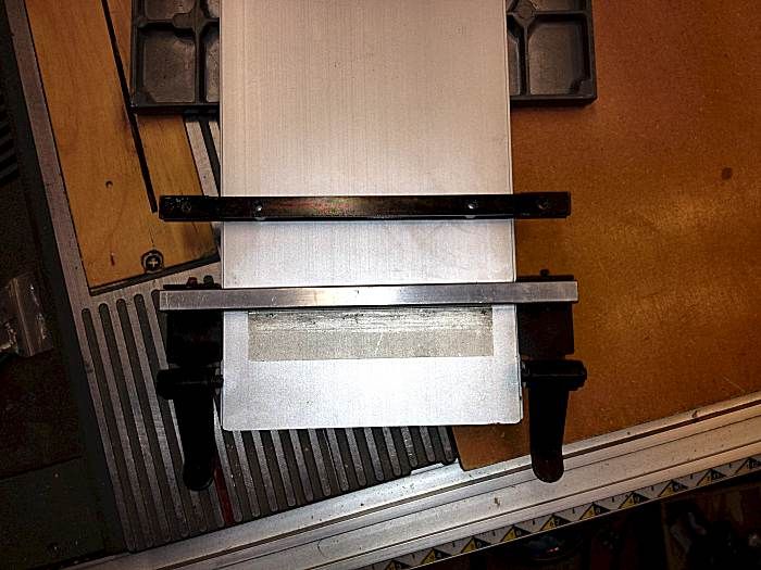
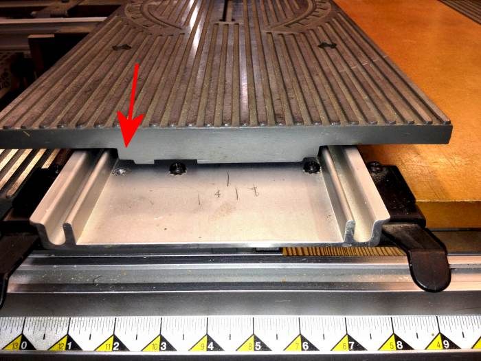
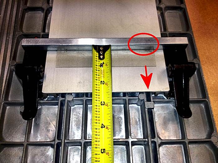
    Having a problem with my sliding miter table. When the table has moved all the way to the back stop, the miter fence has not cleared the saw blade. In fact, it' only about 1" past the centerline of the blade. It needs to go another 3-4" to clear the blade (depending on howhigh it's raised).

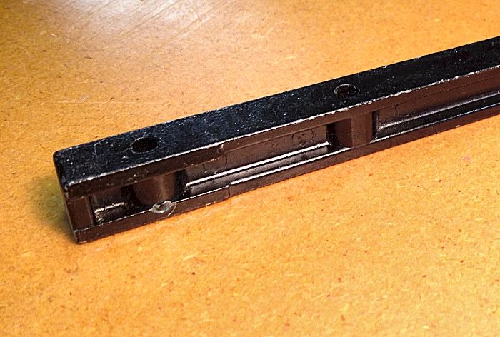
    I've taken it apart and put it back together and searched the forums but am having no luck. Surely this isn't normal. Is it?.
  • LCHIEN
    Internet Fact Checker
    • Dec 2002
    • 20883
    • Katy, TX, USA.
    • BT3000 vintage 1999

    #2
    A couple of quick Q's. Are you using a Sears Craftsman 21829 or a BT3000/3100?
    if a 21829 then are you using the rearmost miter fence or the normal miter fence location? The 21829 has a feature some BT3 owners have done for years which is to place a set of
    pivot hole at the very front of the SMT to allow cross-cutting large objects at 90Deg.
    If you have a 21829 then put the miter fence in the "normal" location which is about a 1/3 of the way up the SMT in the middle of the protractor markings where you can make angles miter cuts rather than the very deep 90deg cut.

    If you are using the normal BT3 miter fence locations, then all I can say is , that I have no problems like yours,,,, try lowering the blade some.
    Loring in Katy, TX USA
    If your only tool is a hammer, you tend to treat all problems as if they were nails.
    BT3 FAQ - https://www.sawdustzone.org/forum/di...sked-questions

    Comment

    • capncarl
      Veteran Member
      • Jan 2007
      • 3563
      • Leesburg Georgia USA
      • SawStop CTS

      #3
      Any chance that you installed the sliding miter table on the saw backwards?
      (180 degrees off) If I remember right it will fit equally well both ways, just no travel when installed backwards.
      capncarl

      Comment

      • Heknits
        Handtools only
        • Oct 2013
        • 4
        • Benicia, CA
        • Ryobi BT3000

        #4
        Relatively certain it's installed correctly for making cuts.

        I guess for 90 degree cuts it will work because the back end of the piece just passes the highest point on the blade, but still odd to have the tables stop without moving the work past the blade and it still doesn't work for angled cuts.

        Lowering the blade doesn't help because the high point is always the centerline of the blade and that's the point I need to pass to finish a cut. It helps if I raise the blade...a lot...but that gets a little hairy.

        I suppose I can make it work by flipping over the piece and reversing the angle of the fence and adding a wood face to my fence will probably get me past the mark. Still seems odd. I have a newer BT3000 so I compared travel on the SMT and the new one moves 3 1/2" further than old one.
        Last edited by Heknits; 10-08-2013, 03:52 PM. Reason: Edited to remove bad photo links

        Comment

        • mpc
          Senior Member
          • Feb 2005
          • 978
          • Cypress, CA, USA.
          • BT3000 orig 13amp model

          #5
          I just took a quick look at my spare SMT. When the sliding work surface portion is pushed as far back as it goes, the plastic guide clips (on the bottom of it - the pieces that connect the work surface to the track) end up right at the end of the aluminum track piece. The actual fence isn't past the entire blade but is well past the highest point/center of the blade. Unlike a true slot-style miter fence, this SMT does not push all the way past the blade.

          Things that can limit the SMT travel:
          1) the screws that attach the slider to the four small plastic guide pieces might be upside-down. The nuts should be in the top of the slider part with the screw heads facing down. If the nuts are on the underside of the slider, they'll likely smack into the clamps that hold the SMT to the saw's fence rails.

          2) there is a small metal tab to lock the slider to the track when you are moving the saw or don't need/want the SMT function. Make sure it isn't hanging down and snagging the end of the track piece; it's supposed to slip into one of the skinny slots cut into the track for the lock function. Otherwise it shouldn't touch anything.

          3) the SMT track is supposed to be mounted with the overhang to the front (infeed) side of the saw. Stores often install it backwards though so it doesn't hang into the isle and snag customers walking by... or they install it backwards by mistake/ignorance.

          mpc
          Last edited by mpc; 10-08-2013, 05:59 PM.

          Comment

          • Lonnie in Orlando
            Senior Member
            • May 2003
            • 649
            • Orlando, FL, USA.
            • BT3000

            #6
            Heknits

            Welcome to the forum.

            I had a problem with the Sliding Miter Table on my BT3000 similar to yours. I solved the problem(s). Maybe this will help you.

            SMT FENCE MOVES PAST SAW BLADE
            The fence on my SMT does in fact move all the way past a fully elevated 10" blade.


            Here are a few things to check that may be preventing your SMT fence from moving all the way past the blade:

            QUICK FOLD OUTFEED TABLE
            If you have a Ryobi Quick Fold outfeed on your saw, it will limit the travel of the SMT. I cut out a section of my QF table to allow the SMT to fully travel to the outfeed side. Also, the SMT may be hitting one of the hinges that connect the table to the saw. I put shims between the hinge leafs on the QF table and between the hinge leafs on the rear rail to lower the hinges.

            Quick Fold Cutout: The SMT stops about 1/4" short of the table.


            GUIDE BAR UNDER THE BASE OF THE SLIDING MITER TABLE
            The Guide Bar may be the problem (part #15 in this diagram on Ray Girling's site):
            < CLICK > to see diagram of SMT

            Bear with me for a few paragraphs ...

            I believe that Ryobi changed the Guide Bars that screw onto the base of the SMT at some time during production. The Guide Bars in the diagram are solid and are drilled/threaded to accept the screws to hold them to the base. The holes in the Guide Bars for the infeed and outfeed ends of the base are in the same position.

            This placement of the screws causes the head of the right screw on the outfeed side of the SMT base to hit a stop on the underside of the SMT. This prevents the fence on the SMT from traveling completely through the saw blade.

            The right hole for the Guide Bar on the outfeed side of my BT3000 was drilled closer to the middle. Different from the infeed side. The screw head does not touch the stop. This placement allows the SMT to travel over the screw head and move the fence completly past the blade. There is another stop a little farther into the underside of the base that hits the screw head and stops movement

            The Guide Bar on my saw was an aluminum channel instead of a drilled square piece. The screws threaded into the sides of the open channel, so they couldn't be overly tightened without stripping out the channel. Needless to say, I stripped it out. The replacement steel Guide Bar that I bought was drilled and threaded like the ones in the diagram.

            The replacement Guide Bar was not reinforced at the location of one of the holes in the outfeed end of the base of my SMT. So I couldn't drill and tap a new hole in it. I had to drill a new hole in the base of the SMT for the screw to mount the Guide Bar. That's when I discovered that the new location of the screw was a problem. I have since replaced the solid Guide Bar with an aluminum channel guide bar like the original one. Here are some pics ...

            The arrow points to the hole that I had to drill for the replacement solid Guide Bar. It is in the same location shown in the diagram. If the screw for your Guide Bar is in this location, then we may have found your problem. The screw head closer to the middle is the original location of the screw for the aluminum Guide Bar.


            Here are two Guide Bars sitting on top of the SMT base. (Just to show, not attached.) The aluminum channel Guide Bar is at the top of the pic. You can see the holes in the solid replacement Guide Bar and the hole that I drilled in the base.


            This is the underside of the outfeed end of my base. The aluminum channel Guide Bar is screwed into place. The solid replacement guide bar is sitting on the base (unattached)


            These are the openings in the outfeed end of the SMT that allow the screw heads for the Guide Bar to pass underneath. (The SMT is sitting on the saw, not in the correct position) There are three openings for screw heads ... the screw heads that mount my aluminum Guide Bar and the screw heads for the solid Guide Bar (red arrow)


            Now, after that long winded dissertation, here is the problem ...
            One of the screw heads for the solid Guide Bar hits a little square casting on the bottom of the SMT that acts as a stop (red arrow). This stops the travel of the SMT a little over 2-inches before the fence can move completely through the blade. The location of the screw that attaches the solid Guide Bar is indicated with a red oval.


            I believe that there is a similar stop a little farther back that catches the screw head for my aluminum Guide Bar that has one of the screws closer to the center. If you grind off the square stop in the photo to allow the fence on your SMT to move fully through the blade, then it may also allow the SMT to slide completely off of the base!

            Remove the SMT from the base. There may be another stop behind the square stop that will prevent the SMT from sliding completely off. (I dunno) If there is another stop or if you can fabricate one, then use your judgement about grinding off the square stop in the photo.

            Whew! My fingers are tired of typing. Hope that I didn't just muddy up the waters.

            - Lonnie
            OLD STUFF ... houses, furniture, cars, wine ... I love it all

            Comment

            • Heknits
              Handtools only
              • Oct 2013
              • 4
              • Benicia, CA
              • Ryobi BT3000

              #7
              Thanks for all the info and photos, Lonnie! I have two BT3000; one with the older style SMT and one newer and ended up pulling apart the SMT on both.
              The older saw has the screws on the infeed and outfeed side both close to the edge. The newer saw has one screw closer to the middle (and that is the saw that will allow full travel past the blade). I hadn't considered grinding down the stop on the older saw, but I'm going to take it apart again and see if there is another stop or if I can fabricate something. At least now I know I'm not going crazy.

              I bought the newer saw for $65 on Craigslist because it had the quick-fold table and a few other accessories I had been wanting for mine, so I appreciate the info about the quick-fold table modification, too.

              Comment

              • Lonnie in Orlando
                Senior Member
                • May 2003
                • 649
                • Orlando, FL, USA.
                • BT3000

                #8
                Glad we solved the mystery. Wonder why the location of the hole for the guide bar was changed (??)

                I squinted between my SMT and the base and saw the stop for the close-spaced screw head cast into the aluminum. Might be possible to fabricate something similar for the wide-spaced screw head if you have the nerve to grind down the square stop.

                Please post an update when you disassemble your SMT. Let us know if you were able to cobble together a new stop. Looks like other forum members have the same problem that you have.

                - Lonnie
                OLD STUFF ... houses, furniture, cars, wine ... I love it all

                Comment

                • Black wallnut
                  cycling to health
                  • Jan 2003
                  • 4715
                  • Ellensburg, Wa, USA.
                  • BT3k 1999

                  #9
                  Why not just move the screw? Drill the correct hole size in the solid bar and if the existing screw is like most other fasteners on the saw and triangular threads it is a thread forming screw. If not then just tap the hole with a tap of the correct size.
                  Donate to my Tour de Cure


                  marK in WA and Ryobi Fanatic Association State President ©

                  Head servant of the forum

                  ©

                  Comment

                  • LCHIEN
                    Internet Fact Checker
                    • Dec 2002
                    • 20883
                    • Katy, TX, USA.
                    • BT3000 vintage 1999

                    #10
                    My solution to the QFT (Quick fold table) was to move the left-side hinge to be behind the main table so the SMT would not hit the hinge. Its then limited in travel by the QFT itself. The miter fence stops somewhere beyond the center of the blade. THis is enough to complete the cut. I don't really have any issues with the blade burnishing the end of the cuts that don't pass the blade.
                    Loring in Katy, TX USA
                    If your only tool is a hammer, you tend to treat all problems as if they were nails.
                    BT3 FAQ - https://www.sawdustzone.org/forum/di...sked-questions

                    Comment

                    • Lonnie in Orlando
                      Senior Member
                      • May 2003
                      • 649
                      • Orlando, FL, USA.
                      • BT3000

                      #11
                      I was going to drill and tap a new hole in the steel guide bar, but there is not enough steel at that location. The bar is like an I-beam. The bars have reinforcements around the holes.


                      Width at tip for the clamp


                      Width at body


                      Perhaps a piece of 1/2" square stock could be drilled and tapped. It may need to be filed down to match the original guide bar. A full half inch bar may scrape against the rails.


                      Aluminum bar thickness


                      The "narrow" holes are 3-1/32" apart. Inside edge to outside edge = center-to-center.


                      - Lonnie
                      Last edited by Lonnie in Orlando; 10-12-2013, 10:44 AM.
                      OLD STUFF ... houses, furniture, cars, wine ... I love it all

                      Comment

                      • Lonnie in Orlando
                        Senior Member
                        • May 2003
                        • 649
                        • Orlando, FL, USA.
                        • BT3000

                        #12
                        Loring -

                        My SMT contacted the QF table for a long time before I cut out a space in the table. You're right, I was able to make cuts completely thought a workpiece, but I just never liked the cut edge so close to the spinning blade. I knicked a few pieces.

                        I never knew that the steel guide bar prevented the SMT from extending fully past the blade until I cut out the QF table.

                        - Lonnie
                        OLD STUFF ... houses, furniture, cars, wine ... I love it all

                        Comment

                        • Heknits
                          Handtools only
                          • Oct 2013
                          • 4
                          • Benicia, CA
                          • Ryobi BT3000

                          #13
                          Originally posted by Black wallnut
                          Why not just move the screw?
                          There is a stop cast into the bottom of the sliding table that is in line with the screw that limits the travel of the table. If you move the screw out of the path of the stop, the table WILL move past the blade...and then right off the end of the rails. There won't be anything to stop it. On the tables with the screw in the alternate location, the stop block on the table is further back, too. The screw is less of an issue than the stop.

                          Comment

                          Working...